Overview
Let’s be honest, we all know that simpler is better. The simplicity of a peristaltic style metering pump makes it a very reliable method for injecting a wide variety of chemicals into water treatment applications. Understanding the variables that result in wear on the pump components, especially wear to the pump tube assembly, can assist the reader in properly specifying the pump for a specific application.
Peristaltic pump technology
The human body uses the “peristalsis” action to move food through the digestive tract. The wave-like muscle contractions progressively squeeze the digestive tract, essentially “pushing” the food through. It doesn’t get any simpler than that.
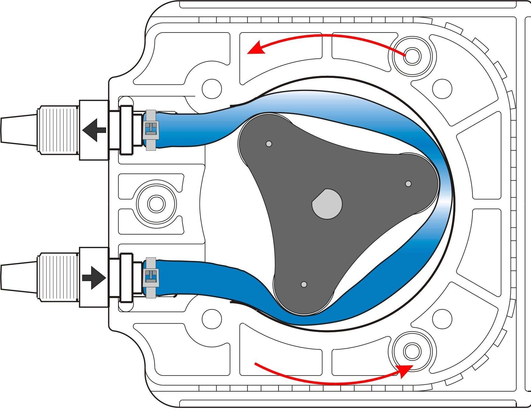
One of the greatest benefits of a peristaltic pump is its functional simplicity. Peristaltic pumps utilize a circular pump “head” and simple rotating roller that is designed to pinch the tubing and gently squeeze the fluid through specially designed tubing, as shown in Figure 1.

They can effectively pump both fluids and gasses, eliminating the possibility of siphoning, vapor locking, or loss of prime even when operating at very low output rates. Nearly continuous output results in a finer dispersion of the chemical in the piping system when compared to pulsating type pumps such as diaphragm pumps. Figure 2 shows the near-continuous output of the chemical in the flow stream when using a peristaltic pump versus the interrupted chemical dispersion when using a diaphragm pump.

Fewer components result in very low maintenance costs when compared to the cost of rebuilding more complex pumps that require a large number of wetted components such as metal springs, o-rings, valves, check balls, etc.
Commonly called a squeeze tube pump, the new generation of peristaltic chemical metering pump is quite different from the low-pressure laboratory pumps most people are familiar with seeing in a hospital setting. These industrial workhorses are now capable of pumping aggressive chemicals such as 12% sodium hypochlorite (chlorine), 50% sodium hydroxide, 97% sulfuric acid, and 85% phosphoric acid against system pressures up to 125 psi. Some models include such features as tube failure detection systems, flow verification sensors and sophisticated control electronics for PLC interface and connection to SCADA systems.
Pump System Components
For analysis purposes, the peristaltic pump assembly can be broken down into five main components; 1. pump tube, 2. pump head and roller, 3. motor, 4. control electronics, and 5. motor/electronics housing. Note that in some models, the control electronics (VFD, motor starter, PLC, etc.) are housed in a separate enclosure.
Variables to tubing wear
Many manufacturers rate the life of their tubing by the number of effective operating hours before failure. While this rating may be effective for comparing the life of tubes used in the same pump under a specific set of operating parameters (for example; pumping water with a specific pump head type, at 0 psi, at a fixed RPM), there are many variables that will affect the number of hours a given tube will last in an actual application. Care should be taken to specify the pump components and operating parameters to achieve the greatest tube life possible in an application.
- Tubing materials – The tubing material must withstand the chemical being injected, return to its original shape after many thousands of occlusions (compressions), and operate at the required system pressure. Specifying the optimum tubing material is critical for a successful application.
- Chemical resistance – Chemical incompatibility will result in a breakdown of the tubing material properties, often manifested as a change in the stiffness of the material, either softening or hardening. In most cases, chemical resistance problems will be apparent within the first few days of use. However, in some cases, the chemical will attack the tubing material slowly over a long period of time, reducing the life of the tube.
- Dimensions – Larger tube diameters and thinner wall thicknesses will generally result in reduced tube life expectancy.
- Material properties – The physical properties of the tubing material will greatly influence not only its suitability for general use in a peristaltic pump but also the amount of time the tube will last in a particular application. The peristaltic pump tube must be capable of precisely returning to its original shape many thousands of times after being squeezed by the roller. Many tubing materials lack this memory-making them unsatisfactory for peristaltic pump applications. Tubing manufacturers offer a variety of tubing formulations, many of which are suitable for use in peristaltic pumps and many which are not. The end-user must be cautious when selecting the tubing material for the application. Most pump suppliers will either offer assistance with the tubing selection or offer pre-assembled “tube assemblies” designed specifically for their peristaltic pumps, greatly reducing the possibility of miss-application.
- System pressure – The pressures acting on the tubing will directly affect the tube’s life. Both the inlet and outlet pressures should be considered and particular attention should be paid to “hidden” variables that can add to the system pressure such as piping system components and fluid viscosity.
- System pressure – The most obvious (and perhaps most influential) variable affecting tube life is the piping system pressure. But often, system components and installation factors that can increase the pressure at the pump tube are overlooked. For example, most manufacturers recommend installing a check valve in the discharge piping directly after the pump tube to prevent the system fluid from flowing back through the pump during routine pump maintenance or pump tube rupture. A spring-loaded check valve or back pressure valve will increase the pressure at the pump tube by a value equal to the cracking pressure of the valve. For example, if the system pressure is 50 psi and the backpressure valve is set at 20 psi, the effective pressure at the pump tube is 70 psi. Therefore, valves with high cracking pressures should be avoided.
- Another often overlooked variable that can increase the pressure at the pump tube is the physical distance from the pump to the point where the chemical is injected into the system, especially important to consider when injecting viscous fluids. The pressure at the pump tube will increase as the distance from the injection point increases, the chemical viscosity increases, and the discharge-piping diameter decreases. Imagine trying to drink a thick milkshake through a skinny, 100-foot straw! Small diameter orifices in fittings should also be avoided when pumping viscous chemicals.
- Number of occlusions – The tube life is affected by the number of times the tubing must be pinched (number of occlusions) in order to pump a given amount of chemical. Reducing the number of occlusions will increase the life of the tube. Four variables affect the number of occlusions required to inject a given amount of fluid; the diameter of the tubing, the diameter of the pump head, the number of rollers on the roller assembly (occlusions per revolution), and the motor rpm. Some manufacturers use the total number of occlusions, rather than time, when estimating their tube life expectancy.
- Tubing diameter – A larger diameter tube will inject more chemical fluid per occlusion (trap more chemical fluid between two pinched rollers) than a smaller diameter tube. Therefore, a large tube can output more chemical fluid with fewer occlusions, resulting in less wear, than a smaller tube.
- Pump Head Diameter – Similar to the tubing diameter, the pump head diameter will affect the amount of chemical per occlusion. Larger diameter pump heads will result in more chemical fluid being pumped per revolution.
- The number of rollers – A given peristaltic pump model may have anywhere from one (offset cam type roller) to six or more individual rollers which squeeze the tube, pinching off the captured fluid and delivering it to the discharge end of the pump tube. Multiple rollers per assembly result in slightly smaller volumes of chemical injection per revolution, less pulsation, and a reduced likelihood that an individual roller will wear out resulting in lost pumping capability. However, since tube life is directly proportional to the number of times the tube is pinched per revolution, the cost associated with the higher number of rollers is tube life.
- Motor rpm – Unlike many types of pumps, peristaltic pumps are capable of operating at very low revolutions per minute (rpm) while maintaining very high accuracy, repeatability, and priming capability. Therefore, to increase tube life, specify the pump so that the typical operation of the pump is at the lower end of the operating output adjustment range, resulting in the fewest number of occlusions. The maximum possible rpm of a specific pump model will vary from manufacturer to manufacturer with maximum motor rpm of 650 being not uncommon, though, at this high rpm, tube life will be greatly diminished. Some pump models have effective turndown ratios of up to 10,000:1 resulting in a minimum effective rpm of 0.01!
- Amount of tubing squeeze – Simply pinching off (occluding) the tube is not enough, the rollers must squeeze the tubing the exact amount required to ensure that the fluid being pumped is effectively trapped in the tubing and delivered to the injection point. Factors such as system pressure, suction lift, fluid viscosity, tube material, and others will affect the amount of squeeze required for a particular application. If the tube is under-squeezed, the fluid can escape or flow backward toward the suction side of the pump tube when the roller rotates in the head. This can occur when the pump is operated against a higher system pressure than recommended. If the tube is squeezed too much, it is being subjected to more force than is necessary and tube life will be diminished. Properly matching the roller design with the type of tube being used will result in the most efficient pump design and longest tube life for a particular application. Figure 3 shows the squeeze action of a peristaltic pump.

Pump Head and Roller Design
The roller diameter, roller materials, type of bearing surfaces, and pump head design can also affect the life of the pump tube as well as the life of the roller assembly. The schematic of a pump head is shown in Figure 4.

Roller diameter – A large diameter roller will pinch off a greater surface area of the tube while rotating, resulting in lower tube life; however, large rollers will rotate fewer revolutions per roller assembly revolution, potentially resulting in longer roller life.
Roller bearings – The roller must rotate on a shaft, therefore the type and design of the bearing surfaces can increase or decrease the life of the roller. The design of the bearing surface can also assist in preventing chemicals and debris (from tubing surface wear) from entering the roller axle area causing drag on the roller.
Roller material – The roller assembly materials of construction should be of sufficient strength to withstand the repeated compressions of the pump tube while offering resistance to the chemicals that may potentially be spilled in the pump head area. The roller assembly must also have the dimensional stability to withstand variations in ambient temperatures and rotational forces without affecting the amount of squeeze on the pump tube.
Pump head – As with the roller assembly, the pump head materials of construction must also withstand any spilled fluid that may enter the head. The diameter of the head will also affect the amount of fluid pumped per revolution, with larger pump heads discharging more chemicals per revolution than smaller pump heads.
All of the parameters such as system pressure, number of occlusions, tube chemical resistance, tube squeeze, and roller bearing inefficiency impact tube life as shown in Figure 5.

Chemical spills – If left alone, the pump tube will eventually fail. Depending on the operating pressure, type of tube, and many other factors, the chemical may leak out slowly or squirt out dramatically. Manufacturers offer a number of different methods for protecting the roller assembly, pump head, and area surrounding the pump from chemical spills. Some manufacturers include drain ports to remove the chemical, float switches to shut down the pump when a spill occurs and a cup fills, and electronic sensors to shut down the pump when the chemical is detected in the pump head area. Some methods are more effective at quickly turning off the pump and reducing the amount of chemical spilled. Based on the effectiveness of the method, the pump head and roller assembly may incur damage resulting in a drag on the roller assembly and reduced roller and tube life.
5.
Motor
A variety of motors ranging from small, fractional horsepower shaded pole AC gear motors, to large C-frame AC and DC powered gear motors are used with peristaltic pumps. Many peristaltic pump manufacturers include the motor as part of the pump assembly which helps take the guesswork out of specifying the correct motor to use for a given pump assembly. As with any pump, care should be taken to properly specify the motor for the pump and the intended operating environment.
Control Electronics
The control electronics must be carefully selected to properly control the motor as well as provide for any remote control and communications capabilities such as analog input motor speed control, analog output pump speed feedback to SCADA, alarm outputs, pump status, etc. As with the motor, many pumps include the control electronics as part of the assembly.
Enclosures
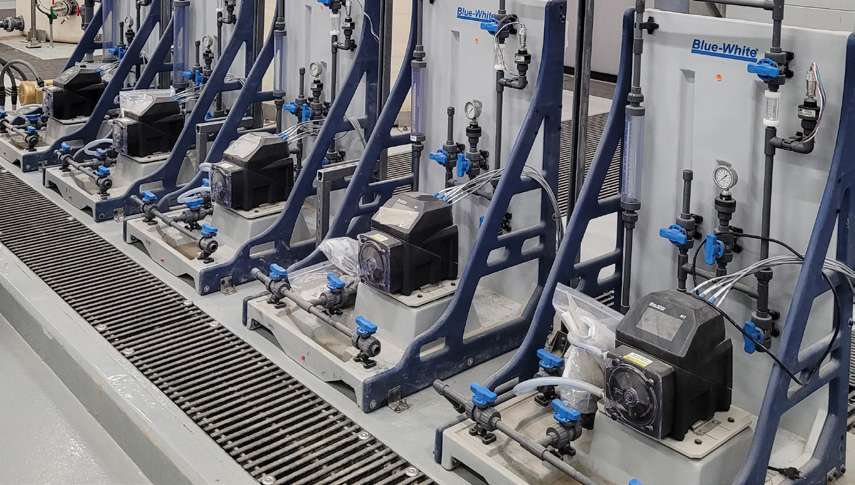
Typically, a peristaltic pump enclosure protects the motor and control electronics from the operating environment while the pump head area of the pump is either unprotected or sealed in its own enclosure separate from the motor and controls. Manufacturers offer a variety of enclosures for the motor and control circuitry ranging from small plastic housings to explosion-proof metal enclosures. Many pumps are supplied without any enclosure at all. As with the motor and control electronics, the user should take care to specify the pump system with a proper enclosure that is designed to provide the protection needed for the application environment, as shown in Figure 6.

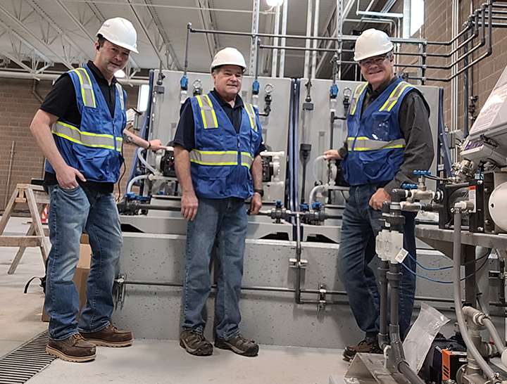
A typical setup of peristaltic pumps with an integral motor and controller that provides the necessary chemical feed to the cooling water system is shown in Figure 7.

Conclusion
Many variables affect the service life and maintenance requirements of a peristaltic pump. By carefully assessing the application, the user can properly specify the pump and components to minimize service and maintenance requirements and maximize the life of the pump.
Mr. Bill McDowell is a Sales Engineer with Blue-White Industries and has over 29 years with the company. He has held various positions with Blue-White Industries including Project Engineer and Director of Engineering. Additional information can be obtained from Blue-White Industries at, 5300 Business Drive, Huntington Beach, CA 92649. Phone 714-893-8529, Fax 714-894-9492, or sales@blue-white.com; www.blue-white.com

